A prototype self-driving car that mimics human ability to drive along roads has been born. Navigation processes images using the concept of visual sir Boeing equipped with camera sensors and uses Python programming to motion control the vehicle position toward the road line (see last video experiment in this story).
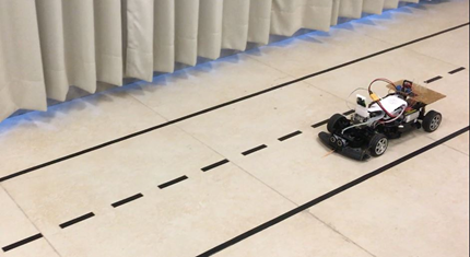
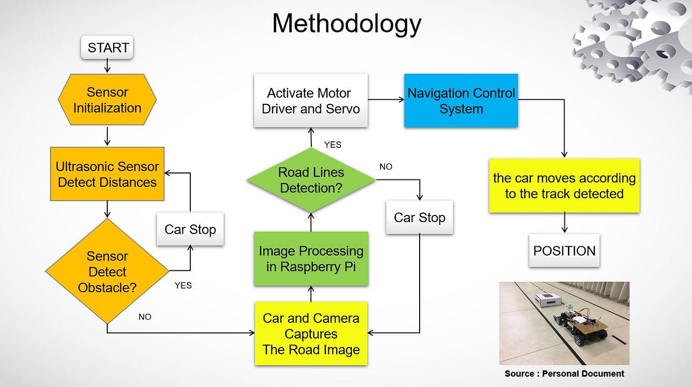
Prototype self-driving cars advance only between straight road markings and one-way lanes. The truck is 11m long, 60cm wide, and has three black road markings with a total turning angle of 90 degrees. There are no intersections and only obstacles in front of the car can be detected. Test in a room with sufficient lighting conditions. The project methodology is shown below.
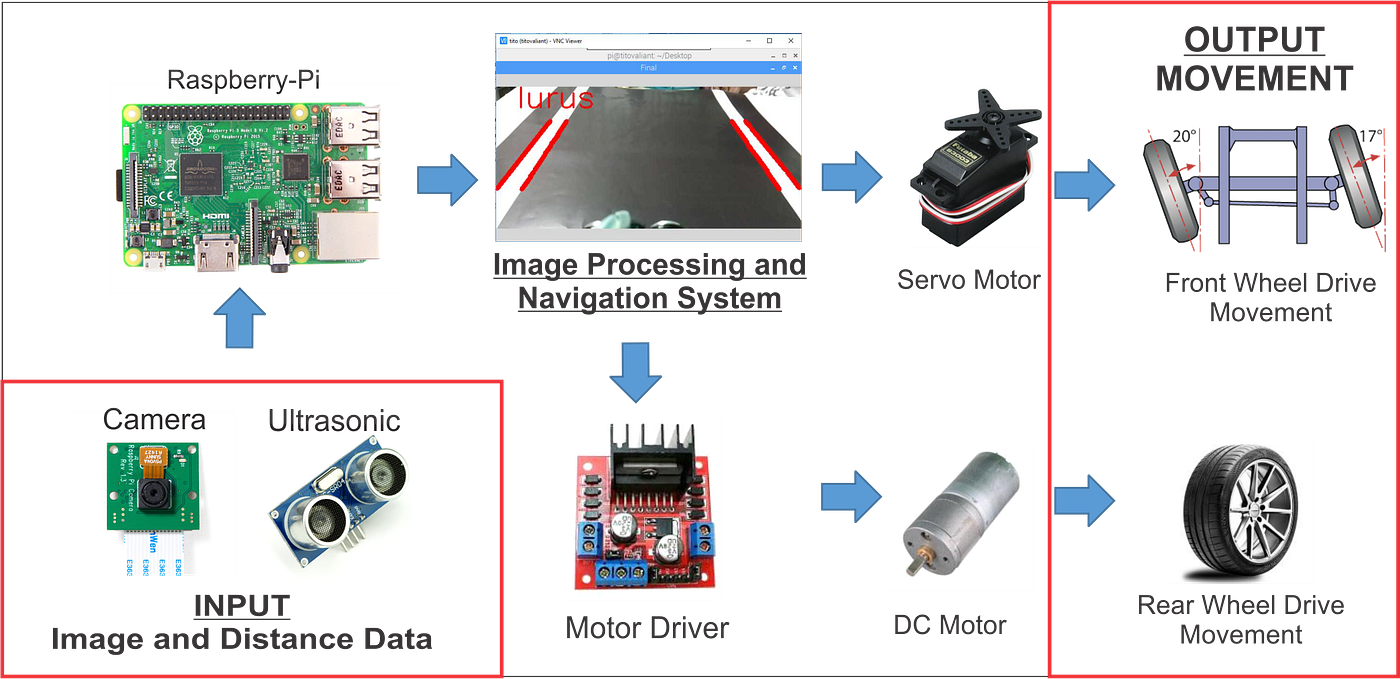
In this paper, a prototype automatic driving vehicle can be used by using ultrasonic sensor to avoid failure of the vehicle, and the vehicle sensor is born. The number crypto camera uses to detect roads, and a visual translation, and a visual translation of the visual conversion, and a road line conversion and a road line sensor. The robot is tested and applies to real time using pie3 model B+.
인기글
![[GOLDEN GOOSE] Genuine Golden Goose Francie Women High Top Glitter Sneakers_ Weaver Lux](https://cdn.mariooutlet.com/Product/A0333/ALQ/P000692735_d1.jpg?RS=520&CS=-1X1000&CG=2 "[GOLDEN GOOSE] Genuine Golden Goose Francie Women High Top Glitter Sneakers_ Weaver Lux")

")

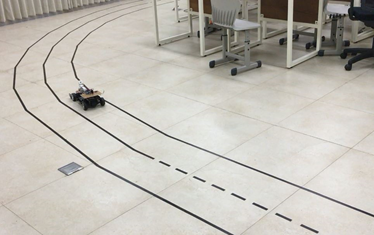
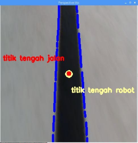
As a result of Image Processing, the center value of the road display x-axis pixel (Titik Tengah jalan) and the camera robot (Titik Tengah robot) move along the road. The purpose of the control system is to maintain the robot’s heading by adjusting the motor servo angle for steering control. Experiments have shown that the robot can automatically travel along both painted and unpainted road markings to avoid obstacles.
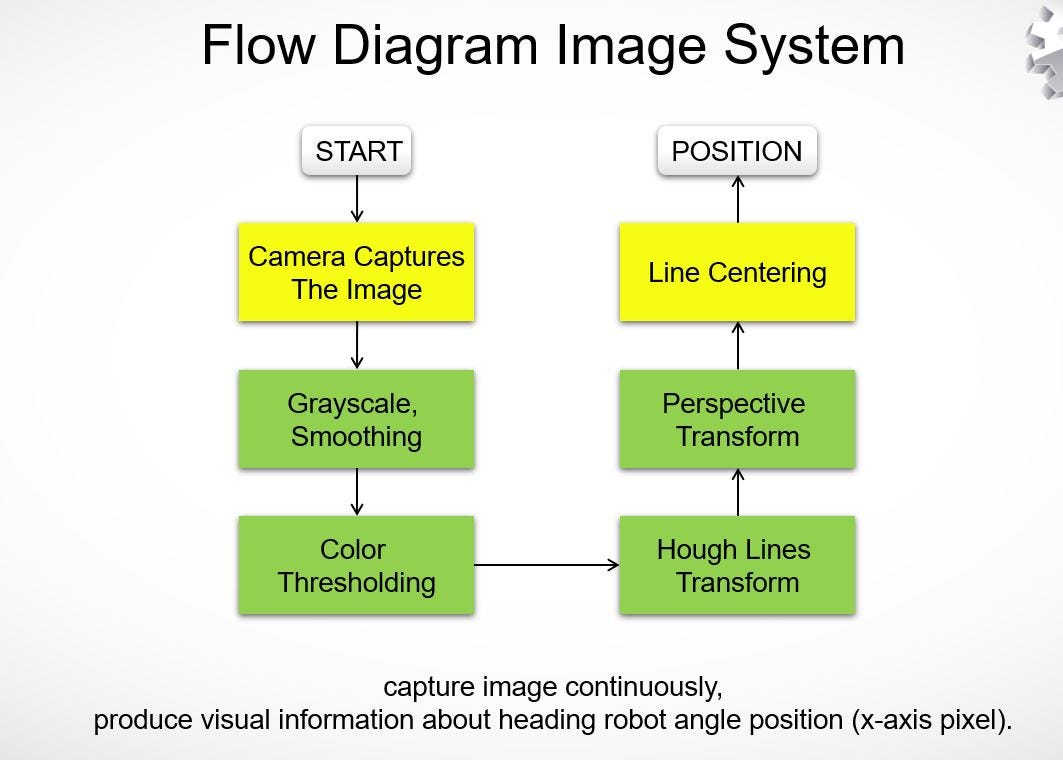
The original size of the image captured in this paper is 448×208 pixels RGB color image. The purpose of the video processing method is to obtain video information data from continuous images on the front of the vehicle through input of a decision module and obtain data necessary to control the movement of the vehicle. The road sign detection procedure is described as follows.
We will now share the step-by-step image processing configuration while the vehicle moves automatically in real time. It is described below.
First of all, the system calls the camera sensor and captures the original image in RGB3 color layer with a 448×208 pixel-sized camera raspberry pie. Using Python Programming and OpenCV, RGB values are a function of object color and overall brightness. The code is described below.
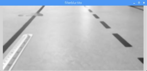
As the second process, I need to convert RGB original image into grayscale image to minimize processing time. The gray-toned image process is minimized compared to RGB color images, and this feature converts 24-bit and 3-channel color images into 8-bit single channel/1 color layers with the OpenCV function of “cv2.cvColor”.
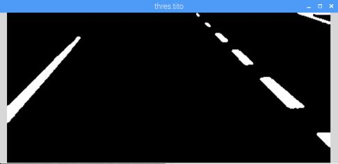
Comparisons between threshold intensity differences or high contrast image pixel points are detected on the road lines.In the experiment, the lower threshold is 127 and the upper threshold is 255 (white).
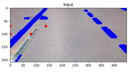
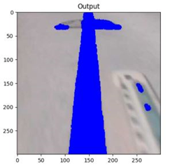
The image processing method for the show logging (color threshold) feature displays the route/ray using the blue line in the previous white. This method requires Open CV feature “cv2″cv2” is required.The results of this method is shown below.
The application of this feature is to use the OpenCV features “cv2.getPerspectiveTransform()” and “cv2.warPerspective()” to select a rectangular pixel point value in a new specific area to obtain a two-dimensional view of the detected upper “bird’s eye” lane. The image (previous) fluoroscopy input is applied as shown below.
For visual information, a specific area along the base pixel point (Red points) to display visual information. A process of detecting only one side/side/side/side surface of the road display, the parameter value of the vehicle can be easily obtained. This feature is 300×300 pixels RGB, only the road display only the road display. The Personal Translation is applied to the following diagram, as below.
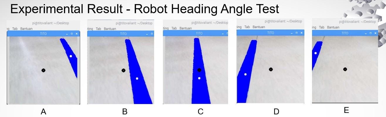
After obtaining a specific area in the Perspective Transform process, the system needs a “cv2.moments()” function to calculate the mid/median center point of an x-axis pixel image of a sensed road sign.
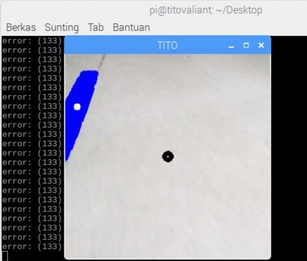
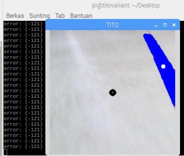
The purpose of this function is to calculate the difference (error) between the center value of the x-axis pixel road display and the intermediate/median value of the robot x-axis pixel. The difference calculation (error value) result is used to adjust the motor servo angle for steering control.The purpose of this function is to calculate the difference (error) between the center value of the x-axis pixel road display and the intermediate/median value of the robot x-axis pixel. The difference calculation (error value) result is used to adjust the motor servo angle for steering control.As you can see from above, if the result of an Error Value is between 130 and 26, the image process will detect a left turn on the road line.If the Error Value (error value) results between -25 and 25 to 25 and 25 to 25 and 25 to 25 to 255.If the result of the error value of Error Value (error value) is between -25 and 25 and 25 and 25 and 25.This is my link of the profile that is my link. You can see my experiment on my automatic driving car.https://www.linkedin.com/posts/titovaliantmuhammad_autonomouscar-pythonprogramming-selfdrivingcar-activity-6592061994877186048-duwl copyright@21 TITAM HAMAM HAMAM HAMERMAM HAMERMAM HAMERMLinkedIn Tito Valiant Muhammad 페이:: #SelfDrivingCar #SelfDrivingCar Prototype SelfDrivingCar with Visual Servo and Python Programming In my project, The Prototype Self Driving Car was automatically created…www.linkedin.comLinkedIn Tito Valiant Muhammad 페이:: #SelfDrivingCar #SelfDrivingCar Prototype SelfDrivingCar with Visual Servo and Python Programming In my project, The Prototype Self Driving Car was automatically created…www.linkedin.comLinkedIn Tito Valiant Muhammad 페이:: #SelfDrivingCar #SelfDrivingCar Prototype SelfDrivingCar with Visual Servo and Python Programming In my project, The Prototype Self Driving Car was automatically created…www.linkedin.com